
To make this possible we needed a create a circuit with some transistors to do the switching. This circuit board also makes the wiring more streamlined and by breaking out the power from the battery to convenient screw terminals.

V_bat is naturally the battery, but one might wonder what V_arduino is. This is the 5V rail on the Arduino, and we use this to power the RC reciever, as this needs stable 5V unlike the rest of the equipment that's designed to run straight off battery.
The transistor
The motor controller can draw a maximum of 3A and so we had to use get some decent sized transistors. We went with the TIP122, a transistor in a TO-220 package that can switch up to 5A. The Pixy and video transmitter dont use that much, but we went with the same type of transistor as they are dead cheap anyways.
Calculating the base resistor
As shown in the circuit diagram in the first image we have a resistor connected to the base of each transistor. The value has been calculated with these neat formulas:

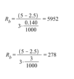
The value of hFE andVbe we get from the dataseheet of the transistor (hFE=1000, Vbe=2.5). The value of Vi is the voltage from the digital pins of the Arduino and is 5V. Ic is 3A for the motor controller and 140mA for the two other outputs.
This gives the values for the different resistors as follows:
Creating the circuit on a PCB
The circuit was created as compact as possible on a prototype PCB. The prototype board had full length copper traces, and we had to cut some of them to be able to get the design compact. This image shows the underside of the circuit.

And this image shows the circuit top-down, with the terminals marked.

No comments:
Post a Comment