Monday, February 16, 2015

What COM port is my device on?

Sometimes it's ok to let the user manually select the COM port where the device is located, other times you want to select the right device automatically.


The following code snippet loops thru all COM ports in search for a specific device ID. The connected port is the printed to a textbox.

ManagementObjectCollection ManObjReturn;
ManagementObjectSearcher ManObjSearch;
ManObjSearch = new ManagementObjectSearcher("Select * from Win32_SerialPort");
ManObjReturn = ManObjSearch.Get();

foreach (ManagementObject ManObj in ManObjReturn)
{
    string deviID = ManObj["PNPDeviceID"].ToString().Split('\\')[1];
    if(deviID == "VID_2341&PID_0001") // Arduino uno devID
    {
        richTextBox1.AppendText("\nArduino uno is connected on  "
            + ManObj["DeviceID"].ToString());
        break;
    }
}

The devID might be a bit confusing, but we are just splitting a long string to get the relevant info. At the end of the PNPDeviceID it is also appended a counter, starting at 1 and incrementing in case you have many identical devices attached.
The code requires importing a reference to System.Management

Friday, February 13, 2015

SolidWorks 3D high quality render

We have rendered the 3D model with more realistic lighting, and higher quality settings. The results are nice, but it now takes a good few minutes to render each image (using 128xAA might explain some of that)


Creating a power routing PCB

To get some battery life on our rig we needed to be able to switch off the power to some of the real power draining equipment for when they are not needed. Especially the motor controller, but also the video transmitter and even the Pixy can some times be turned off to save power.

To make this possible we needed a create a circuit with some transistors to do the switching. This circuit board also makes the wiring more streamlined and by breaking out the power from the battery to convenient screw terminals.

The image above shows the circuit diagram for the circuit. The transistors are connected to digital pins on the Arduino (Arduino_D1 is digital pin 1).

V_bat is naturally the battery, but one might wonder what V_arduino is. This is the 5V rail on the Arduino, and we use this to power the RC reciever, as this needs stable 5V unlike the rest of the equipment that's designed to run straight off battery.

The transistor
The motor controller can draw a maximum of 3A and so we had to use get some decent sized transistors. We went with the TIP122, a transistor in a TO-220 package that can switch up to 5A. The Pixy and video transmitter dont use that much, but we went with the same type of transistor as they are dead cheap anyways.

Calculating the base resistor
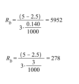
As shown in the circuit diagram in the first image we have a resistor connected to the base of each transistor. The value has been calculated with these neat formulas:


The value of hFE andVbe we get from the dataseheet of the transistor (hFE=1000, Vbe=2.5). The value of Vi is the voltage from the digital pins of the Arduino and is 5V. Ic is 3A for the motor controller and 140mA for the two other outputs.
This gives the values for the different resistors as follows:

Creating the circuit on a PCB
The circuit was created as compact as possible on a prototype PCB. The prototype board had full length copper traces, and we had to cut some of them to be able to get the design compact. This image shows the underside of the circuit.

And this image shows the circuit top-down, with the terminals marked.


Wednesday, February 11, 2015

Improving the motion tracking

Objects

So far our program has just been detecting motion in general, but in order to use this program for our rig we needed to output more information about what we had detected. There are many sources for movement in an image, like wind blowing on a tree in the background. We needed to filter out those kind of movements as they are just noise to us. To be able to do this we had to implement a routine to separate the motion in a frame into different objects.

Separating objects are done during the processing of each image. This processing occurs pixel by pixel throughout the entire image. A routine is called every time a changed pixel is detected. The location of this pixel is then checked against the border of the existing objects to see if it is close enough to be part of the object.

The images below illustrates the processing of a image where a changed pixel is detected and appended to an existing object.


If no object is within range of the changed pixel there will be created a new object to house it. The limits for how near two pixels have to be can be adjusted, but a test with a distance of 2 gave good results.

Object center and vector

When the image is fully processed the method outputs a list of objects detected. These objects are then checked by size. The largest object is considered the most important and is prioritized for further processing. The other objects are discarded to save memory.

The center of this object is the found by the following formula:


And the object center is then used to calculate the vector from the object to the middle of the screen, by using this formula:


The resulting vector can then be used further down the road to control the motors on the rig.
These images are the actual output of  the program:

Black/white (white signals movement):

And color:

3D modelling the final rig

We are starting to see our project take form. We have decided on and ordered most of the parts we need, like motor controller, processor and camera. And that means we are now ready to design the housing for these parts.

The housing is made to be mounted on a regular tripod and the rig will be able to revolve 360 degrees. The camera will be mounted in the cradle on top to allow tilt.

We've sketched the rig in SolidWorks, to use as a construction drawing later. The model will be further refined to with mounts for the different circuit boards, batteries and cameras.

Animated 3D model:


The rig rendered in exploded view:


We have access to a machine shop and will be building the rig from aluminium sheet to get a sturdy and light construction.

Monday, February 9, 2015

Built a gimbal to test the controller

About a week ago we recieved our gimbal controller, and started working on getting it up and running. However it's not so easy to tune PID parameters and get an idea of how the rig will be if you cant test it.

Lucky for us we are cleared to use the machine shop at the school and so we decided to go down there and create our very own gimbal assembly for testing.

A few hours at the shop yielded this beauty:


Since we are also going to 3D model the final rig i figured i could brush up my 3D skills by making a model of this test rig as well.

The model was made with Solid Works. Here is the result:


You can download the SolidWorks 3D model from the following link. With measurements and everything. The motors were downloaded from grabcad.com, a great resource.
https://drive.google.com/file/d/0B9x-J0iccTH4TXJXc3VvQXBsdDg/view?usp=sharing


Friday, February 6, 2015

Simple motion tracking


Background
The Pixy camera offers motion tracking thru color recognition. This works well with strong colors like glow-in-the-dark paint and such, but was not ideal for our project. We knew we had to modify the Pixy to get a more general tracking of motion.

To make it easier to work with, and to be able to visualize the output of the algorithms we decided to start working with the code base for Pixymon. Pixymon is the PC host for Pixy, that lets you change settings and view real-time motion tracking.

The idea is that once we get the code working nicely on our computer with Pixymon it will be possible to then port that code over to run on the Pixy.

The code
In the Pixymon codebase we added a method inside the renderer class to run our own algorithm on the video stream before it was shown on screen. This proved a good place to start as the video stream at this point in the code is broken down to individual pixels with corresponding x and y coordinates in each frame.

To avoid problems with color setting the RGB picture was first converted to greyscale by mixing all three channels like this:

gray = (R +G + B)/3

 -First, simple motion detection
We then created a simple algorithm that checks each pixel against the corresponding pixel in the last frame. Thresholding is used to remove small differences like uneven lighting.


If a pixel has changed since last the pixel is painted white. Else it is painted black.
This gives a fast and easy motion detection. The result can be shown in the picture below, and is a screenshot made when moving a hand in front of the camera:


Now this is a very simple process, and we will have to expand it with filtering and maths. But for now it's a good starting point for further work. 

The images are only 318x198 piksler due to a limitation on the transfer rate from the Pixy over USB. On the Pixy internally the resolution will be alot better.