When we decided on which motors we were to use for the platform, the main consideration was that they had to provide continous and smooth motion. Smooth motion is a requirement if the rig is to be used for recording video, and it might also be less scary for nearby wildlife.
BLDC motors were chosen, as they seemed to be the best option for smooth motion. However when we started writing our own code for the motorcontroller, we ran into some problems with a previously unknown fenomena, known as cogging.
Cogging is the uneven turning-resistance in electromotors due to different factors, one of which is the magnets passing over the stators, causing periodic peaks in turning resistance.
When running BLDC motors at low RPM's these effects become very pronounced. And the whole rig was continously shivering from torque ripple when turning.
The solution to this problem was implementing a gyroscope and a PID controller. The PID controller compensates for the motors uneven torque response, and the result is smooth rotation.
The first video is the platform without any compensation for cogging:
And this second video is after gyro and PID was introduced:
There are still some fine tuning left to do with the PID parameters.

Thursday, May 21, 2015
Monday, May 18, 2015
The next version of the AimBot?
The project is coming to an end, and the last couple of weeks have been spent writing a report on the work we have done. We have also been doing a round of testing, and will be publishing a video on that matter sometime soon.
In the meantime you can check out this rendering of the AimBot with 3 axis:

In the meantime you can check out this rendering of the AimBot with 3 axis:

Tuesday, April 28, 2015
Wednesday, April 8, 2015
The 3D model is updated
The rig needed a bit more power and so we bought some more appropriately sized motors. And as such the 3D model had to be revised. There have also been a few other adjustments, one being that the arm holding the camera is now hinged on both sides by the addition of a ball bearing oposite of the upper motor.
We couldn't find any premade models of the new motors we bought so we made some sketches ourselves. The result is not incredibly photo-realistic, but at least the measurements are in order.
Here is a quick render and a few images:
We couldn't find any premade models of the new motors we bought so we made some sketches ourselves. The result is not incredibly photo-realistic, but at least the measurements are in order.
Here is a quick render and a few images:
 |
| Current version of the rig |
 |
| And a render in exlploded view |
 |
| And this is how it looks when working with it in SolidWorks |
 |
| And for comparison this is the actual rig in it's current unpolished state |
Friday, March 27, 2015
Reading PWM
Background
The AimBot rig is to be controlled remotely. To achieve this we are using a standard RC remote of the same type that's normally used with RC cars and planes. The reciever for this unit uses very little power, and is in a very handy size for our rig.


The AimBot rig is to be controlled remotely. To achieve this we are using a standard RC remote of the same type that's normally used with RC cars and planes. The reciever for this unit uses very little power, and is in a very handy size for our rig.
 |
| The control and reciever |
The reciever puts out a PWM signal, and every joystick and button is designated it's own PWM chanel,
For our rig we will be using 4 chanels:
- X-axis joystick
- Y-axis joystick
- Mode switch
- Picture trigger
Every chanel is input to separate digital pins on the Arduino.
Interrupts
In the Arduino program every pin gets set up with a hardware interrupt that runs a interrupt function when the pin state changes. This interrupt is run immediately when the state changes, and interrupts all other code execution. After the interrupt routine is run the code returns to whatever it was doing before it got interrupted.
The code that runs during the interrupt checks the state of the pin that called the interrupt and checks the current time from the internal microseconds counter. The next time the pin state changes the last recorded time is subtracted from the current time, which gives the length of the pulse. The pulse length is then stored in a global variable so it can be accessed by other parts of the program. The image above shows the PWM pulse, where T is one of the pulse lengths we want to measure.
Time and memory
The function code uses micros() to get the current time, this returns a unsigned long (32 bit), that overflows every 70 minutes or so.
Elapsed time is stored in a uint16, this gives us the ability to measure frequencies down to 15 Hz before overflow occurs. The picture below shows the calculation regarding this:
The lowest possible frequency for the PWM signal is around 50 Hz, giving us good margins before overflow.
The counter value is also declared volatile to remove the write-protection, allowing the value to be updated from the interrupt without interfering with the rest of the program.
Advantages over other methods
The Arduino has a ready made library for reading pulse-width modulated signals. The function sigin() can be used for this purpose. We considered using this function, but upon closer examination we decided not to. The reason is that the sigin() function hangs upon call, until the pulse has passed. For a 50 Hz signal this would use about 20 ms per chanel.
Reading the signal using interrupts on the other hand only records the current time of every pass and allows the rest of the program code to continue executing almost immediately.
Monday, March 9, 2015
Battery guard
We are using Li-Po batteries for our rig, and in order to keep them in good condition for a long time it is very important that you dont discharge them too much.
So in order to prevent over-discharge we created a circuit that would let the rig fully disconnect from the battery when the voltage get too low.
We had already made a power management module that lets the Arduino control the power to the other components of the rig. What we now needed was a circuit that would enable the Arduino to switch off it's own power supply.
This turned out to be a bit tricky when designing a transistor based circuit. When the voltage supplied to the Arduino goes too low you loose control over the state of the digital pins. This resulted in the Arduino leaking current to the digital pins, leaving the Arduino in a state of limbo between fully on and fully off.
There are ways of solving this using pull-down resistors and transistors with lower gain, however since it was absolutely imperative that the circuit would not leak any current in the off-state we opted to go with a relay in place of the transistor.

The above picture shows the full circuit for the battery guard.
Some comments to the circuit:
Arduino_A2 - Reads the battery voltage
Arduino_A1 - Reads the state of the ON/OFF button
Arduino_D1 - Outputs 5V, holding the relay and keeping the Arduino alive
So in order to prevent over-discharge we created a circuit that would let the rig fully disconnect from the battery when the voltage get too low.
We had already made a power management module that lets the Arduino control the power to the other components of the rig. What we now needed was a circuit that would enable the Arduino to switch off it's own power supply.
This turned out to be a bit tricky when designing a transistor based circuit. When the voltage supplied to the Arduino goes too low you loose control over the state of the digital pins. This resulted in the Arduino leaking current to the digital pins, leaving the Arduino in a state of limbo between fully on and fully off.
There are ways of solving this using pull-down resistors and transistors with lower gain, however since it was absolutely imperative that the circuit would not leak any current in the off-state we opted to go with a relay in place of the transistor.
The above picture shows the full circuit for the battery guard.
Some comments to the circuit:
Arduino_A2 - Reads the battery voltage
Arduino_A1 - Reads the state of the ON/OFF button
Arduino_D1 - Outputs 5V, holding the relay and keeping the Arduino alive
Monday, February 16, 2015
What COM port is my device on?
Sometimes it's ok to let the user manually select the COM port where the device is located, other times you want to select the right device automatically.

The following code snippet loops thru all COM ports in search for a specific device ID. The connected port is the printed to a textbox.
ManagementObjectCollection ManObjReturn;
ManagementObjectSearcher ManObjSearch;
ManObjSearch = new ManagementObjectSearcher("Select * from Win32_SerialPort");
ManObjReturn = ManObjSearch.Get();

foreach (ManagementObject ManObj in ManObjReturn)
{
    string deviID = ManObj["PNPDeviceID"].ToString().Split('\\')[1];
    if(deviID == "VID_2341&PID_0001") // Arduino uno devID
    {
        richTextBox1.AppendText("\nArduino uno is connected on  "
            + ManObj["DeviceID"].ToString());
        break;
    }
}
The devID might be a bit confusing, but we are just splitting a long string to get the relevant info. At the end of the PNPDeviceID it is also appended a counter, starting at 1 and incrementing in case you have many identical devices attached.
The code requires importing a reference to System.Management
Friday, February 13, 2015
SolidWorks 3D high quality render
We have rendered the 3D model with more realistic lighting, and higher quality settings. The results are nice, but it now takes a good few minutes to render each image (using 128xAA might explain some of that)


Creating a power routing PCB
To get some battery life on our rig we needed to be able to switch off the power to some of the real power draining equipment for when they are not needed. Especially the motor controller, but also the video transmitter and even the Pixy can some times be turned off to save power.
To make this possible we needed a create a circuit with some transistors to do the switching. This circuit board also makes the wiring more streamlined and by breaking out the power from the battery to convenient screw terminals.
 The image above shows the circuit diagram for the circuit. The transistors are connected to digital pins on the Arduino (Arduino_D1 is digital pin 1).
V_bat is naturally the battery, but one might wonder what V_arduino is. This is the 5V rail on the Arduino, and we use this to power the RC reciever, as this needs stable 5V unlike the rest of the equipment that's designed to run straight off battery.
The transistor
The motor controller can draw a maximum of 3A and so we had to use get some decent sized transistors. We went with the TIP122, a transistor in a TO-220 package that can switch up to 5A. The Pixy and video transmitter dont use that much, but we went with the same type of transistor as they are dead cheap anyways.
Calculating the base resistor
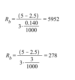
As shown in the circuit diagram in the first image we have a resistor connected to the base of each transistor. The value has been calculated with these neat formulas:

The value of hFE andVbe we get from the dataseheet of the transistor (hFE=1000, Vbe=2.5). The value of Vi is the voltage from the digital pins of the Arduino and is 5V. Ic is 3A for the motor controller and 140mA for the two other outputs.
This gives the values for the different resistors as follows:
Creating the circuit on a PCB
The circuit was created as compact as possible on a prototype PCB. The prototype board had full length copper traces, and we had to cut some of them to be able to get the design compact. This image shows the underside of the circuit.

And this image shows the circuit top-down, with the terminals marked.

To make this possible we needed a create a circuit with some transistors to do the switching. This circuit board also makes the wiring more streamlined and by breaking out the power from the battery to convenient screw terminals.
V_bat is naturally the battery, but one might wonder what V_arduino is. This is the 5V rail on the Arduino, and we use this to power the RC reciever, as this needs stable 5V unlike the rest of the equipment that's designed to run straight off battery.
The transistor
The motor controller can draw a maximum of 3A and so we had to use get some decent sized transistors. We went with the TIP122, a transistor in a TO-220 package that can switch up to 5A. The Pixy and video transmitter dont use that much, but we went with the same type of transistor as they are dead cheap anyways.
Calculating the base resistor
As shown in the circuit diagram in the first image we have a resistor connected to the base of each transistor. The value has been calculated with these neat formulas:
The value of hFE andVbe we get from the dataseheet of the transistor (hFE=1000, Vbe=2.5). The value of Vi is the voltage from the digital pins of the Arduino and is 5V. Ic is 3A for the motor controller and 140mA for the two other outputs.
This gives the values for the different resistors as follows:
Creating the circuit on a PCB
The circuit was created as compact as possible on a prototype PCB. The prototype board had full length copper traces, and we had to cut some of them to be able to get the design compact. This image shows the underside of the circuit.
And this image shows the circuit top-down, with the terminals marked.
Wednesday, February 11, 2015
Improving the motion tracking
Objects
So far our program has just been detecting motion in general, but in order to use this program for our rig we needed to output more information about what we had detected. There are many sources for movement in an image, like wind blowing on a tree in the background. We needed to filter out those kind of movements as they are just noise to us. To be able to do this we had to implement a routine to separate the motion in a frame into different objects.Separating objects are done during the processing of each image. This processing occurs pixel by pixel throughout the entire image. A routine is called every time a changed pixel is detected. The location of this pixel is then checked against the border of the existing objects to see if it is close enough to be part of the object.
The images below illustrates the processing of a image where a changed pixel is detected and appended to an existing object.


If no object is within range of the changed pixel there will be created a new object to house it. The limits for how near two pixels have to be can be adjusted, but a test with a distance of 2 gave good results.
Object center and vector
When the image is fully processed the method outputs a list of objects detected. These objects are then checked by size. The largest object is considered the most important and is prioritized for further processing. The other objects are discarded to save memory.
The center of this object is the found by the following formula:

And the object center is then used to calculate the vector from the object to the middle of the screen, by using this formula:

The resulting vector can then be used further down the road to control the motors on the rig.
These images are the actual output of the program:
Black/white (white signals movement):

And color:

3D modelling the final rig
We are starting to see our project take form. We have decided on and ordered most of the parts we need, like motor controller, processor and camera. And that means we are now ready to design the housing for these parts.
The housing is made to be mounted on a regular tripod and the rig will be able to revolve 360 degrees. The camera will be mounted in the cradle on top to allow tilt.
We've sketched the rig in SolidWorks, to use as a construction drawing later. The model will be further refined to with mounts for the different circuit boards, batteries and cameras.
Animated 3D model:
The rig rendered in exploded view:

We have access to a machine shop and will be building the rig from aluminium sheet to get a sturdy and light construction.
The housing is made to be mounted on a regular tripod and the rig will be able to revolve 360 degrees. The camera will be mounted in the cradle on top to allow tilt.
We've sketched the rig in SolidWorks, to use as a construction drawing later. The model will be further refined to with mounts for the different circuit boards, batteries and cameras.
Animated 3D model:
The rig rendered in exploded view:
We have access to a machine shop and will be building the rig from aluminium sheet to get a sturdy and light construction.
Monday, February 9, 2015
Built a gimbal to test the controller
About a week ago we recieved our gimbal controller, and started working on getting it up and running. However it's not so easy to tune PID parameters and get an idea of how the rig will be if you cant test it.
Lucky for us we are cleared to use the machine shop at the school and so we decided to go down there and create our very own gimbal assembly for testing.
A few hours at the shop yielded this beauty:

Since we are also going to 3D model the final rig i figured i could brush up my 3D skills by making a model of this test rig as well.
The model was made with Solid Works. Here is the result:
You can download the SolidWorks 3D model from the following link. With measurements and everything. The motors were downloaded from grabcad.com, a great resource.
https://drive.google.com/file/d/0B9x-J0iccTH4TXJXc3VvQXBsdDg/view?usp=sharing
Lucky for us we are cleared to use the machine shop at the school and so we decided to go down there and create our very own gimbal assembly for testing.
A few hours at the shop yielded this beauty:
The model was made with Solid Works. Here is the result:
You can download the SolidWorks 3D model from the following link. With measurements and everything. The motors were downloaded from grabcad.com, a great resource.
https://drive.google.com/file/d/0B9x-J0iccTH4TXJXc3VvQXBsdDg/view?usp=sharing
Friday, February 6, 2015
Simple motion tracking

Background
The Pixy camera offers motion tracking thru color recognition. This works well with strong colors like glow-in-the-dark paint and such, but was not ideal for our project. We knew we had to modify the Pixy to get a more general tracking of motion.
To make it easier to work with, and to be able to visualize the output of the algorithms we decided to start working with the code base for Pixymon. Pixymon is the PC host for Pixy, that lets you change settings and view real-time motion tracking.
The idea is that once we get the code working nicely on our computer with Pixymon it will be possible to then port that code over to run on the Pixy.
The code
In the Pixymon codebase we added a method inside the renderer class to run our own algorithm on the video stream before it was shown on screen. This proved a good place to start as the video stream at this point in the code is broken down to individual pixels with corresponding x and y coordinates in each frame.
To avoid problems with color setting the RGB picture was first converted to greyscale by mixing all three channels like this:
gray = (R +G + B)/3
-First, simple motion detection
We then created a simple algorithm that checks each pixel against the corresponding pixel in the last frame. Thresholding is used to remove small differences like uneven lighting.

If a pixel has changed since last the pixel is painted white. Else it is painted black.
This gives a fast and easy motion detection. The result can be shown in the picture below, and is a screenshot made when moving a hand in front of the camera:

Now this is a very simple process, and we will have to expand it with filtering and maths. But for now it's a good starting point for further work.
The images are only 318x198 piksler due to a limitation on the transfer rate from the Pixy over USB. On the Pixy internally the resolution will be alot better.
Friday, January 30, 2015
Connecting a GoPro remote to an Arduino

Why
To make the camera rig do what we wanted it to we needed a way for the Arduino to trigger the camera. A normal DSLR would have a connector for external shutter, but on our rig we would be using a GoPro camera.
So how do you connect a GoPro to an Arduino?
Well, cutting the case and soldering to the GoPro internals was an option, but not a good one. Modifying the remote control however was a less scary endevour.
How?
We opened the remote up, cut a small hole in the case and soldered two wires to the pins of the record button.

We then made a simple transistor circuit that shorts V1 to GND, exactly the same as the button does on the control. This image shows the circuit before it got wrapped in heat shrink.

The remote also still works as a normal remote. We could also fill the remote with glue to make it waterproof again, but that will be a future mod.

This is the circuit layout. Notice the arduino and the remote shares GND. We can do this since the remote control uses a battery, otherwise we would have used a optocoupler in place of the transistor to safeguard against voltage differences.

Project overview shot
We are creating a motion tracking wildlife camera

We might have been a bit unclear earlier about what we were really trying to achieve in this project.
This is a concept drawing that describes the system we are going to create. The whole project will be put in a nice box in the end, so you can mount it on any normal tripod.
Subscribe to:
Comments (Atom)